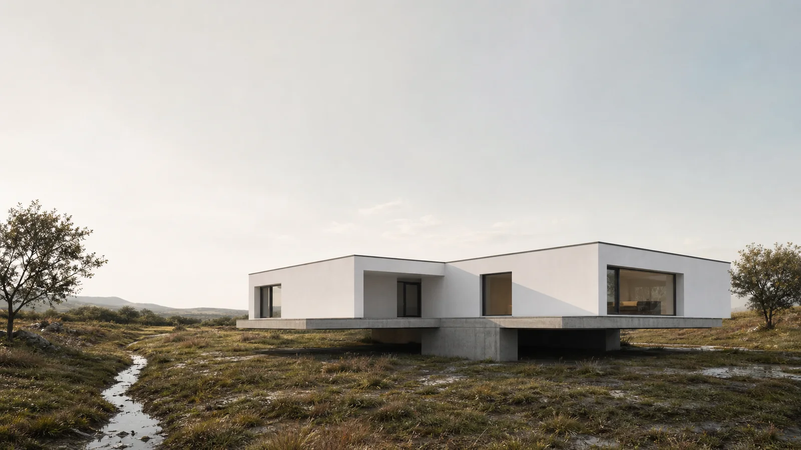
NOARQ’s Chaves House lifts a 324 m² intervention above a plot where water emerges from the ground. A cross-shaped concrete plinth, an inverted-cross plan and drainage to a nearby watercourse turn that wet-site condition into the organizing logic of the house.
Chaves House was built from 2018 to 2024 on a 3,276 m² rustic parcel at the edge of Chaves, near São Neutel Fort. NOARQ, led on the project by José Carlos Nunes de Oliveira, describes a swampy site behind an informal residential area with incomplete urban infrastructure.
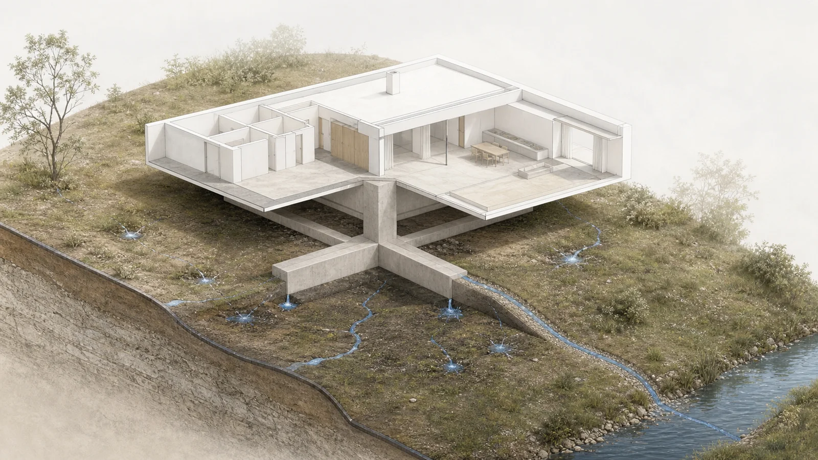
Elevation alone does not route water through the plot. The plinth and suspended edges reduce contact with wet ground, while the drainage system reportedly channels emerging water to a nearby watercourse.
- 3,276 m²
- rustic plot area
- 324 m²
- intervention area, including covered exterior space
- 18 × 18 m
- square that contains the plan
- 4.40 m
- reported building height
Chaves House is a single-storey home in Chaves, Portugal, designed by NOARQ. José Carlos Nunes de Oliveira is credited as the architect, João Morgado photographed the completed project, and the published material record combines reinforced concrete with insulated white walls, an insulated flat roof and thermal-break aluminium glazing.
The 324 m² intervention figure includes covered outdoor area, so it is not a net internal floor-area figure. That boundary keeps the suspended exterior living zones separate from the enclosed room area when the project dimensions are compared.
A 3,276 m² plot the land-use plan classes as a watercourse
Chaves House begins with a planning description rather than a stylistic idea. The project text quotes the Chaves Municipal Land Use Plan classifying the parcel as “Watercourses and their banks with a width of 10 meters.” That wording is the plan’s classification, not a Tallbox legal interpretation of the property.
NOARQ records groundwater emerging across the land and crossing the parcel before reaching an unpaved street. The gentle slope directed that water through ground that remained wet enough for the studio to describe it as swampy.
Incomplete infrastructure, a limited construction budget and the lack of an established urban pattern narrowed the construction options, so NOARQ derived the form from the ground condition. The site became the project’s reference system.
A cross-shaped plinth and an inverted-cross plan reduce ground contact
Chaves House occupies an 18 by 18 metre square above a cross-shaped plinth. The floor plan reverses that geometry, so the inhabited polygon forms an inverted cross while its outer edges project beyond the primary points of support.
The cross-shaped plinth and inverted-cross plan reduce the area where structure meets the wet terrain. The suspended perimeter reveals that separation as a thin horizontal plane rather than a continuous foundation wall. At plan and foundation scales, both geometries reduce ground contact.
NOARQ places the single-storey house midway down the slope and reports a building height of 4.40 metres. It should not be read as the clearance beneath every suspended edge.
Drainage, not just elevation, manages the water on site
NOARQ reports a complex drainage system that directs groundwater to a nearby watercourse. NOARQ and e-architect state that route, but neither source publishes pipe sizes, storage volume, design storms or measured performance.
The structure limits contact between the occupied floor and wet ground, while the drainage system channels water moving through the plot. Reading one without the other reduces a combined site strategy to a single architectural gesture.
The combined elevation and drainage strategy explains NOARQ’s description of the house as mediation between architecture and nature. The form leaves room for water beneath and around the building, while the drainage system reportedly routes groundwater away from the house.
Reinforced concrete, EPS and double glazing on a tight budget
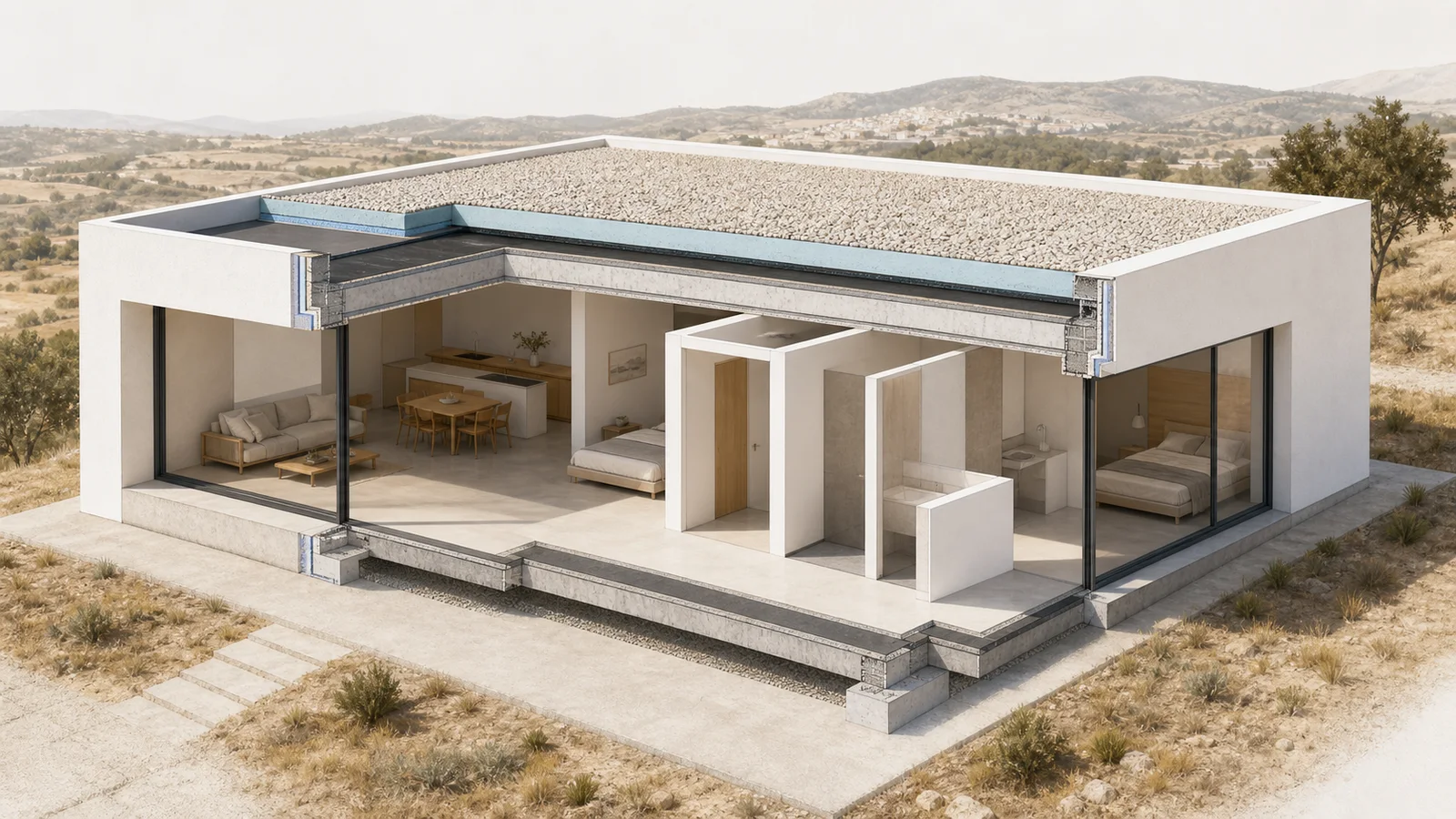
A reinforced-concrete structure supports the elevated floor of Chaves House. The exterior walls receive high-density expanded polystyrene, a rigid foam wall insulation, plus reinforcing mesh and white-pigmented mortar. That build-up turns insulation and finish into a continuous pale envelope around the concrete frame.
Inside, dry gypsum board forms the ceilings and partitions. The service void between the suspended ceiling and roof slab carries the published plumbing and heating installations in one horizontal zone.
The flat roof contains 120 mm of extruded polystyrene, a rigid foam roof insulation, beneath a protective layer of rolled pebbles. Low-profile aluminium frames with a thermal break hold low-emissivity double glazing. NOARQ relates this material sequence to the limited budget and regional temperature range.
NOARQ and e-architect identify products and assemblies but publish no final construction cost or measured energy results. For Chaves House, that material sequence encloses the structure raised above the wet plot without claiming measured performance.
One opening per façade, tuned for Trás-os-Montes summers
Each façade of Chaves House carries one large opening. Interior partitions divide each opening between the rooms it serves, avoiding a row of unrelated windows across the elevation.
Each opening forms a sheltered exterior living area facing the landscape. Deep recesses and the projecting floor plane shade the threshold, linking the glazing strategy to outdoor occupation rather than flattening the windows into the elevation.
NOARQ links the arrangement, orientation, recess depth and large openings to passive solar control during the hot, dry summers of Trás-os-Montes. Neither NOARQ nor e-architect publishes a solar model, shading factor or indoor-temperature study. The opening strategy adds passive-solar intent to the ground-contact and drainage response of Chaves House.
Drainage and elevation evidence that matters before the finish photography
Chaves House returns the site condition to the foreground before its finishes. João Morgado’s photographs can reveal the gap below the floor, the suspended edges and the relationship between the white volume and the terrain. Those visible facts clarify the design, but they do not verify hidden drainage performance.
For readers comparing architecture with property communication, Tallbox’s guide to showing flood-risk site context separates visible grade and drainage cues from address-specific records and engineering evidence. Chaves House applies the same difference between what images show and records establish at project scale.
The plinth gap and projecting edges belong in the image record because they are visible architectural decisions. The land-use classification and reported drainage route belong in the written record because photographs cannot establish either one. Capacity, condition and maintenance would require project documents or site-specific professional review.
- Look for the plinth gap and suspended perimeter in exterior views.
- Read the terrain, visible wet ground and slope as site context.
- Use the published material record for the roof, wall and glazing assemblies.
- Use plans, drainage records and professional review for hidden system capacity or condition.
The four-part evidence order keeps the architecture legible without asking finish photography to prove more than it can show. Reading the ground strategy first keeps the white envelope tied to the site and the terrain within the architectural account.